what capacitance, when added in parallel to the load, changet he power factor to 1
In electrical engineering, the ability factor of an AC ability system is divers as the ratio of the existent power absorbed by the load to the credible power flowing in the circuit, and is a dimensionless number in the airtight interval of −1 to ane. A power gene magnitude of less than one indicates the voltage and current are not in stage, reducing the average product of the two. Real power is the instantaneous production of voltage and current and represents the capacity of the electricity for performing piece of work. Credible power is the product of RMS current and voltage. Due to free energy stored in the load and returned to the source, or due to a non-linear load that distorts the wave shape of the current fatigued from the source, the credible power may be greater than the existent ability. A negative power cistron occurs when the device (which is commonly the load) generates power, which then flows back towards the source.
In an electric power system, a load with a depression power factor draws more current than a load with a high ability cistron for the same amount of useful ability transferred. The college currents increment the energy lost in the distribution system and require larger wires and other equipment. Considering of the costs of larger equipment and wasted energy, electrical utilities will usually charge a higher cost to industrial or commercial customers where at that place is a low power factor.
Power-factor correction increases the ability factor of a load, improving efficiency for the distribution system to which it is attached. Linear loads with a depression power gene (such as consecration motors) tin be corrected with a passive network of capacitors or inductors. Not-linear loads, such as rectifiers, distort the electric current fatigued from the system. In such cases, agile or passive ability factor correction may exist used to annul the baloney and raise the power factor. The devices for correction of the power factor may be at a central substation, spread out over a distribution system, or built into power-consuming equipment.
Linear fourth dimension-invariant circuits [edit]
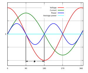
Power flow calculated from AC voltage and current entering a load having a nada power factor (ϕ = 90°, cos(ϕ) = 0). The blue line shows the instantaneous ability entering the load: all of the energy received during the outset (or third) quarter bicycle is returned to the grid during the second (or fourth) quarter cycle, resulting in an average power flow (calorie-free blue line) of naught.
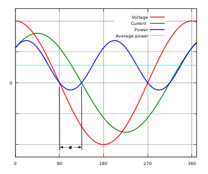
Instantaneous and average power calculated from Air-conditioning voltage and current for a load with a lagging ability factor (ϕ = 45°, cos(ϕ) ≈ 0.71). The blue line (instantaneous power) shows that a portion of the free energy received by the load is returned to the grid during the role of the cycle labeled ϕ.
Linear time-invariant circuits (referred to simply as linear circuits for the balance of this article), for example, circuits consisting of combinations of resistors, inductors and capacitors have a sinusoidal response to the sinusoidal line voltage.[ane] A linear load does not modify the shape of the input waveform but may change the relative timing (phase) between voltage and current, due to its inductance or capacitance.
In a purely resistive AC circuit, voltage and current waveforms are in pace (or in phase), changing polarity at the same instant in each cycle. All the power inbound the load is consumed (or prodigal).
Where reactive loads are present, such as with capacitors or inductors, energy storage in the loads results in a phase deviation between the current and voltage waveforms. During each cycle of the AC voltage, extra energy, in addition to whatsoever energy consumed in the load, is temporarily stored in the load in electric or magnetic fields and so returned to the ability grid a fraction of the period later on.
Electrical circuits containing predominantly resistive loads (incandescent lamps, heating elements) have a power gene of almost i, but circuits containing anterior or capacitive loads (electric motors, solenoid valves, transformers, fluorescent lamp ballasts, and others) can have a power factor well below 1.
In the electrical power grid, reactive loads cause a continuous "ebb and menstruation" of nonproductive power. A circuit with a low power factor will utilize a greater amount of current to transfer a given quantity of real power than a circuit with a high power factor thus causing increased losses due to resistive heating in ability lines, and requiring the utilise of higher-rated conductors and transformers.
Definition and calculation [edit]
AC power has two components:
Together, they form the complex power ( ) expressed as volt-amperes (VA). The magnitude of the complex power is the apparent power ( ), also expressed in volt-amperes (VA).


The VA and var are not-SI units mathematically identical to the watt, only are used in engineering practice instead of the watt to state what quantity is being expressed. The SI explicitly disallows using units for this purpose or equally the merely source of data about a physical quantity as used.[four]
The power factor is defined as the ratio of real power to apparent power. As ability is transferred along a transmission line, information technology does not consist purely of existent ability that can do work in one case transferred to the load, but rather consists of a combination of real and reactive power, called apparent ability. The power cistron describes the amount of real ability transmitted forth a transmission line relative to the full credible ability flowing in the line.[5] [half-dozen]
The power gene can also exist computed as the cosine of the angle θ by which the electric current waveform lags or leads the voltage waveform,[seven].
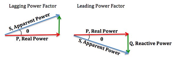
Power triangle [edit]

One can chronicle the various components of Air-conditioning power by using the power triangle in vector space. Real power extends horizontally in the existent axis and reactive ability extends in the direction of the imaginary centrality. Circuitous power (and its magnitude, credible power) represents a combination of both real and reactive power, and therefore tin can be calculated by using the vector sum of these ii components. We tin can conclude that the mathematical relationship between these components is:
![{\displaystyle {\begin{aligned}S&=P+jQ\\[2pt]|S|&={\sqrt {P^{2}+Q^{2}}}\\{\text{pf}}={\frac {P}{|S|}}&=\cos {\theta }=\cos {\left(\arctan {\left({\frac {Q}{P}}\right)}\right)}\\Q&=P\,\tan(\arccos({\text{pf}}))\end{aligned}}}](https://wikimedia.org/api/rest_v1/media/math/render/svg/cdde08a641c22fa5103dea02c8e8dde1bc537cc0)
As the angle θ increases with fixed total apparent power, current and voltage are further out of stage with each other. Real power decreases, and reactive ability increases.
Lagging and leading ability factors [edit]
Ability factor is described as leading if the current waveform is avant-garde in phase with respect to voltage, or lagging when the electric current waveform is backside the voltage waveform. A lagging power factor signifies that the load is anterior, as the load will "consume" reactive power. The reactive component is positive equally reactive power travels through the circuit and is "consumed" by the inductive load. A leading power cistron signifies that the load is capacitive, as the load "supplies" reactive ability, and therefore the reactive component is negative as reactive ability is being supplied to the circuit.

If θ is the phase bending between the current and voltage, then the ability factor is equal to the cosine of the angle, :


Since the units are consistent, the power gene is past definition a dimensionless number between −one and 1. When power factor is equal to 0, the energy flow is entirely reactive and stored energy in the load returns to the source on each cycle. When the power gene is one, all the free energy supplied by the source is consumed by the load. Ability factors are usually stated every bit "leading" or "lagging" to evidence the sign of the phase angle. Capacitive loads are leading (electric current leads voltage), and inductive loads are lagging (current lags voltage).
If a purely resistive load is connected to a ability supply, electric current and voltage volition modify polarity in step, the power cistron volition exist i, and the electric energy flows in a unmarried direction across the network in each cycle. Inductive loads such every bit induction motors (any type of wound coil) consume reactive power with the current waveform lagging the voltage. Capacitive loads such every bit capacitor banks or buried cables generate reactive ability with the current phase leading the voltage. Both types of loads will absorb energy during role of the Ac wheel, which is stored in the device'due south magnetic or electric field, only to return this energy back to the source during the rest of the cycle.
For example, to get i kW of existent ability, if the power factor is unity, 1 kVA of apparent power needs to be transferred (1 kW ÷ 1 = 1 kVA). At depression values of ability factor, more apparent ability needs to be transferred to become the same existent power. To go i kW of real power at 0.ii power gene, v kVA of apparent power needs to be transferred (1 kW ÷ 0.2 = 5 kVA). This apparent power must exist produced and transmitted to the load and is subject to losses in the production and manual processes.
Electrical loads consuming alternating current ability consume both real power and reactive ability. The vector sum of real and reactive power is the complex power, and its magnitude is the apparent power. The presence of reactive ability causes the real power to be less than the credible power, and then, the electric load has a power factor of less than one.
A negative ability factor (0 to −ane) can result from returning agile power to the source, such as in the case of a edifice fitted with solar panels when surplus power is fed back into the supply.[8] [nine] [10]
Power factor correction of linear loads [edit]

Power factor correction of linear load
A high power factor is generally desirable in a ability delivery organization to reduce losses and improve voltage regulation at the load. Compensating elements near an electrical load will reduce the apparent power demand on the supply system. Power factor correction may be applied by an electrical power transmission utility to improve the stability and efficiency of the network. Private electrical customers who are charged by their utility for depression power factor may install correction equipment to increase their ability factor then equally to reduce costs.
Power factor correction brings the power factor of an Air-conditioning power excursion closer to 1 past supplying or absorbing reactive power, calculation capacitors or inductors that act to abolish the inductive or capacitive effects of the load, respectively. In the example of offsetting the anterior effect of motor loads, capacitors can exist locally connected. These capacitors help to generate reactive ability to run across the demand of the inductive loads. This will go on that reactive ability from having to catamenia all the way from the utility generator to the load. In the electricity industry, inductors are said to consume reactive power and capacitors are said to supply it, fifty-fifty though reactive power is just free energy moving dorsum and forth on each AC cycle.
The reactive elements in power factor correction devices can create voltage fluctuations and harmonic racket when switched on or off. They will supply or sink reactive power regardless of whether there is a corresponding load operating nearby, increasing the system's no-load losses. In the worst example, reactive elements can interact with the organisation and with each other to create resonant conditions, resulting in system instability and severe overvoltage fluctuations. As such, reactive elements cannot simply be applied without engineering assay.

An automatic power factor correction unit consists of a number of capacitors that are switched by means of contactors. These contactors are controlled by a regulator that measures ability gene in an electric network. Depending on the load and power factor of the network, the power cistron controller will switch the necessary blocks of capacitors in steps to brand sure the power factor stays above a selected value.
In place of a set of switched capacitors, an unloaded synchronous motor can supply reactive ability. The reactive power drawn by the synchronous motor is a function of its field excitation. It is referred to as a synchronous condenser. Information technology is started and connected to the electric network. It operates at a leading power factor and puts vars onto the network as required to support a system's voltage or to maintain the system power factor at a specified level.
The synchronous condenser's installation and operation are identical to those of large electrical motors. Its chief advantage is the ease with which the amount of correction tin can exist adapted; it behaves like a variable capacitor. Unlike with capacitors, the amount of reactive power supplied is proportional to voltage, non the square of voltage; this improves voltage stability on big networks. Synchronous condensers are oftentimes used in connectedness with high-voltage direct-current transmission projects or in large industrial plants such as steel mills.
For power factor correction of high-voltage ability systems or big, fluctuating industrial loads, power electronic devices such every bit the static VAR compensator or STATCOM are increasingly used. These systems are able to compensate sudden changes of power factor much more speedily than contactor-switched capacitor banks and, existence solid-country, require less maintenance than synchronous condensers.
Non-linear loads [edit]
Examples of non-linear loads on a power system are rectifiers (such as used in a power supply), and arc discharge devices such as fluorescent lamps, electrical welding machines, or arc furnaces. Considering current in these systems is interrupted past a switching action, the current contains frequency components that are multiples of the power system frequency. Baloney ability factor is a measure of how much the harmonic baloney of a load electric current decreases the boilerplate power transferred to the load.

Sinusoidal voltage and non-sinusoidal current give a baloney power factor of 0.75 for this computer power supply load.
Non-sinusoidal components [edit]
In linear circuits having only sinusoidal currents and voltages of one frequency, the power cistron arises only from the difference in phase between the current and voltage. This is "displacement power factor".[11]
Non-linear loads change the shape of the current waveform from a sine wave to some other grade. Non-linear loads create harmonic currents in addition to the original (fundamental frequency) Ac current. This is of importance in practical power systems that contain non-linear loads such every bit rectifiers, some forms of electric lighting, electric arc furnaces, welding equipment, switched-way power supplies, variable speed drives and other devices. Filters consisting of linear capacitors and inductors can prevent harmonic currents from inbound the supplying organization.
To measure the real power or reactive power, a wattmeter designed to work properly with non-sinusoidal currents must be used.
Baloney power factor [edit]
The distortion power factor is the distortion component associated with the harmonic voltages and currents present in the system.

is the total harmonic distortion of the load current.


is the fundamental component of the current and is the total current – both are root mean foursquare-values (distortion power factor tin also exist used to describe individual order harmonics, using the corresponding current in identify of total electric current). This definition with respect to full harmonic baloney assumes that the voltage stays undistorted (sinusoidal, without harmonics). This simplification is oftentimes a skillful approximation for stiff voltage sources (non being affected by changes in load downstream in the distribution network). Total harmonic baloney of typical generators from current baloney in the network is on the order of 1–2%, which can take larger calibration implications merely tin be ignored in common practice.[12]


The result when multiplied with the deportation ability factor (DPF) is the overall, true power gene or just power factor (PF):

Baloney in three-stage networks [edit]
In do, the local effects of baloney electric current on devices in a three-phase distribution network rely on the magnitude of sure order harmonics rather than the total harmonic baloney.
For example, the triplen, or zero-sequence, harmonics (3rd, 9th, 15th, etc.) have the property of being in-phase when compared line-to-line. In a delta-wye transformer, these harmonics tin effect in circulating currents in the delta windings and result in greater resistive heating. In a wye-configuration of a transformer, triplen harmonics will not create these currents, merely they will consequence in a non-zero current in the neutral wire. This could overload the neutral wire in some cases and create error in kilowatt-hour metering systems and billing acquirement.[13] [14] The presence of current harmonics in a transformer also result in larger eddy currents in the magnetic core of the transformer. Eddy electric current losses mostly increase as the foursquare of the frequency, lowering the transformer's efficiency, dissipating additional heat, and reducing its service life.[15]
Negative-sequence harmonics (fifth, 11th, 17th, etc.) combine 120 degrees out of phase, similarly to the fundamental harmonic but in a reversed sequence. In generators and motors, these currents produce magnetic fields which oppose the rotation of the shaft and sometimes result in damaging mechanical vibrations.[xvi]
Switched-mode power supplies [edit]
A particularly important course of non-linear loads is the millions of personal computers that typically incorporate switched-style power supplies (SMPS) with rated output power ranging from a few watts to more than than 1 kW. Historically, these very-low-cost ability supplies incorporated a simple total-wave rectifier that conducted only when the mains instantaneous voltage exceeded the voltage on the input capacitors. This leads to very high ratios of superlative-to-average input current, which also lead to a low distortion power cistron and potentially serious stage and neutral loading concerns.
A typical switched-mode ability supply commencement converts the Ac mains to a DC bus by means of a bridge rectifier. The output voltage is and so derived from this DC omnibus. The problem with this is that the rectifier is a non-linear device, so the input current is highly non-linear. That means that the input electric current has energy at harmonics of the frequency of the voltage. This presents a problem for power companies, because they cannot compensate for the harmonic electric current by adding simple capacitors or inductors, as they could for the reactive power fatigued by a linear load. Many jurisdictions are beginning to require ability factor correction for all power supplies above a sure power level.
Regulatory agencies such as the Eu have set up harmonic limits as a method of improving power factor. Declining component cost has hastened implementation of two different methods. To comply with current Eu standard EN61000-3-2, all switched-manner power supplies with output power more than than 75 W must at least include passive power gene correction. 80 Plus power supply certification requires a ability factor of 0.9 or more.[17]
Power factor correction (PFC) in non-linear loads [edit]
Passive PFC [edit]
The simplest manner to control the harmonic current is to use a filter that passes electric current only at line frequency (50 or 60 Hz). The filter consists of capacitors or inductors and makes a non-linear device look more than like a linear load. An instance of passive PFC is a valley-make full circuit.
A disadvantage of passive PFC is that it requires larger inductors or capacitors than an equivalent power active PFC circuit.[18] [19] [twenty] Besides, in practice, passive PFC is oft less effective at improving the ability factor.[21] [22] [23] [24] [25]
Active PFC [edit]
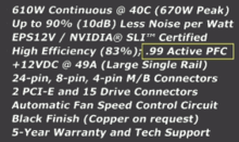
Specifications taken from the packaging of a 610 Due west PC power supply showing active PFC rating
Agile PFC is the use of ability electronics to alter the waveform of current drawn past a load to amend the ability factor.[26] Some types of the active PFC are buck, heave, buck-boost and synchronous condenser. Active power factor correction can be single-stage or multi-phase.
In the case of a switched-mode power supply, a boost converter is inserted between the bridge rectifier and the main input capacitors. The boost converter attempts to maintain a constant voltage at its output while drawing a electric current that is ever in phase with and at the same frequency every bit the line voltage. Another switched-way converter inside the power supply produces the desired output voltage from the DC passenger vehicle. This arroyo requires boosted semiconductor switches and command electronics but permits cheaper and smaller passive components. Information technology is often used in practise.
For a three-phase SMPS, the Vienna rectifier configuration may exist used to substantially improve the power factor.
SMPSs with passive PFC tin can accomplish power factor of virtually 0.7–0.75, SMPSs with agile PFC, up to 0.99 power factor, while a SMPS without any ability factor correction have a power factor of merely almost 0.55–0.65.[27]
Due to their very wide input voltage range, many power supplies with active PFC tin can automatically adapt to operate on Air conditioning ability from about 100 V (Japan) to 240 Five (Europe). That characteristic is particularly welcome in power supplies for laptops.
Dynamic PFC [edit]
Dynamic power gene correction (DPFC), sometimes referred to as "real-time power factor correction," is used for electrical stabilization in cases of rapid load changes (e.one thousand. at large manufacturing sites). DPFC is useful when standard power gene correction would cause over or under correction.[28] DPFC uses semiconductor switches, typically thyristors, to chop-chop connect and disconnect capacitors or inductors to improve power factor.
Importance in distribution systems [edit]
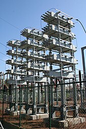
75 MVAr capacitor bank in a 150 kV substation
Power factors below i.0 crave a utility to generate more the minimum volt-amperes necessary to supply the real power (watts). This increases generation and manual costs. For example, if the load ability gene were equally low as 0.7, the credible power would be i.four times the real power used by the load. Line electric current in the excursion would besides exist 1.4 times the current required at ane.0 power gene, so the losses in the circuit would be doubled (since they are proportional to the foursquare of the current). Alternatively, all components of the system such equally generators, conductors, transformers, and switchgear would be increased in size (and toll) to carry the extra electric current. When the power gene is close to unity, for the same kVA rating of the transformer more load current can be supplied.[29]
Utilities typically charge additional costs to commercial customers who accept a power factor beneath some limit, which is typically 0.9 to 0.95. Engineers are often interested in the power factor of a load as i of the factors that affect the efficiency of power manual.
With the rise price of energy and concerns over the efficient commitment of power, active PFC has become more common in consumer electronics.[thirty] Current Energy Star guidelines for computers[31] call for a ability factor of ≥ 0.9 at 100% of rated output in the PC'due south ability supply. According to a white paper authored past Intel and the U.S. Environmental Protection Bureau, PCs with internal power supplies will require the use of active power gene correction to meet the ENERGY STAR 5.0 Programme Requirements for Computers.[32]
In Europe, EN 61000-three-2 requires ability factor correction be incorporated into consumer products.
Small customers, such every bit households, are non normally charged for reactive ability so power factor metering equipment for such customers will not exist installed.
Measurement techniques [edit]
The power factor in a single-phase excursion (or balanced iii-phase circuit) can be measured with the wattmeter-ammeter-voltmeter method, where the ability in watts is divided by the product of measured voltage and current. The power factor of a balanced polyphase circuit is the same as that of any phase. The power factor of an unbalanced polyphase circuit is non uniquely defined.
A straight reading power gene meter can be fabricated with a moving curl meter of the electrodynamic blazon, carrying two perpendicular coils on the moving part of the instrument. The field of the instrument is energized by the excursion current catamenia. The ii moving coils, A and B, are continued in parallel with the excursion load. One coil, A, will be continued through a resistor and the 2d gyre, B, through an inductor, then that the current in curlicue B is delayed with respect to current in A. At unity ability factor, the current in A is in stage with the circuit electric current, and coil A provides maximum torque, driving the musical instrument pointer toward the one.0 mark on the scale. At zero ability gene, the electric current in roll B is in stage with circuit electric current, and coil B provides torque to drive the pointer towards 0. At intermediate values of power gene, the torques provided past the two coils add and the arrow takes up intermediate positions.[33]
Another electromechanical instrument is the polarized-vane type.[34] In this instrument a stationary field coil produces a rotating magnetic field, just like a polyphase motor. The field coils are connected either straight to polyphase voltage sources or to a phase-shifting reactor if a single-phase application. A second stationary field coil, perpendicular to the voltage coils, carries a electric current proportional to current in ane phase of the excursion. The moving system of the musical instrument consists of two vanes that are magnetized by the current coil. In operation, the moving vanes take up a physical angle equivalent to the electrical bending between the voltage source and the current source. This type of instrument tin be made to register for currents in both directions, giving a four-quadrant brandish of ability factor or phase angle.
Digital instruments exist that directly measure the time lag betwixt voltage and current waveforms. Low-toll instruments of this blazon measure the superlative of the waveforms. More sophisticated versions measure the peak of the fundamental harmonic only, thus giving a more than accurate reading for phase bending on distorted waveforms. Calculating power cistron from voltage and current phases is simply accurate if both waveforms are sinusoidal.[35]
Power Quality Analyzers, often referred to as Power Analyzers, make a digital recording of the voltage and current waveform (typically either one phase or three phase) and accurately summate true ability (watts), apparent ability (VA) power factor, Air conditioning voltage, AC current, DC voltage, DC current, frequency, IEC61000-3-ii/3-12 Harmonic measurement, IEC61000-iii-iii/3-11 flicker measurement, individual stage voltages in delta applications where there is no neutral line, total harmonic distortion, phase and aamplitude of private voltage or current harmonics, etc.[36] [37]
Mnemonics [edit]
English-linguistic communication power engineering science students are advised to remember: "ELI the Ice homo" or "ELI on Water ice" – the voltage E, leads the current I, in an inductor Fifty. The current I leads the voltage E in a capacitor C.
Some other common mnemonic is "Ceremonious" – in a capacitor (C) the current (I) leads voltage (V), voltage (V) leads current (I) in an inductor (L).
References [edit]
- ^ Das, J. C. (2015). Ability Organisation Harmonics and Passive Filter Design. Wiley, IEEE Press. p. 2. ISBN978-1-118-86162-ii.
To distinguish between linear and nonlinear loads, nosotros may say that linear time-invariant loads are characterized so that an application of a sinusoidal voltage results in a sinusoidal flow of current.
- ^ Boylestad, Robert (2002-03-04). Introductory Excursion Assay (10th ed.). p. 857. ISBN978-0-xiii-097417-4.
- ^ "SI Units – Electricity and Magnetism". CH: International Electrotechnical Committee. Archived from the original on 2007-12-eleven. Retrieved fourteen June 2013.
- ^ The International System of Units (SI) [SI brochure] (PDF). § five.3.2 (p. 132, 40 in the PDF file): BIPM. 2006.
{{cite book}}: CS1 maint: location (link) - ^ Authoritative Dictionary of Standards Terms (7th ed.), IEEE, 2000, ISBN978-0-7381-2601-2, Std. 100
- ^ Trial-Use Standard Definitions for the Measurement of Electrical Power Quantities Under Sinusoidal, Nonsinusoidal, Balanced, or Unbalanced Conditions, IEEE, 2000, ISBN978-0-7381-1963-2, Std. 1459–2000 . Notation 1, section three.i.1.1, when defining the quantities for power factor, asserts that real power but flows to the load and tin can never be negative. As of 2013, 1 of the authors acknowledged that this annotation was incorrect, and is being revised for the next edition. Run into http://powerstandards.com/Shymanski/draft.pdf Archived 2016-03-04 at the Wayback Machine
- ^ Suresh Kumar, Grand. S. (2013). Electric Circuit Analysis. Pearson. p. 8.x. ISBN978-8-13-179155-four.
- ^ Duddell, West. (1901), "On the resistance and electromotive forces of the electric arc", Philosophical Transactions of the Royal Society A: Mathematical, Concrete and Engineering Sciences, 203 (359–371): 512–15, doi:10.1098/rsta.1904.0022,
The fact that the solid arc has, at depression frequencies, a negative ability factor, indicates that the arc is supplying power to the alternator…
- ^ Zhang, S. (July 2006), "Analysis of some measurement issues in bushing power factor tests in the field", IEEE Transactions on Power Commitment, 21 (3): 1350–56, doi:10.1109/tpwrd.2006.874616, S2CID 39895367,
…(the measurement) gives both negative power factor and negative resistive current (power loss)
- ^ Almarshoud, A. F.; et al. (2004), "Performance of Grid-Continued Consecration Generator under Naturally Commutated AC Voltage Controller", Electric Power Components and Systems, 32 (7): 691–700, doi:10.1080/15325000490461064, S2CID 110279940,
Accordingly, the generator will consume active power from the grid, which leads to negative power factor.
- ^ Ewald Fuchs; Mohammad A. South. Masoum (xiv July 2015). Ability Quality in Power Systems and Electrical Machines. Elsevier Science. pp. 432–. ISBN978-0-12-800988-viii.
The DPF it the cosine of the angle between these two quantities
- ^ Sankaran, C. (1999), Effects of Harmonics on Ability Systems, Electro-Examination,
...and voltage-fourth dimension relationship deviates from the pure sine function. The distortion at the point of generation is very minor (about 1% to 2%), just even so it exists.
- ^ "Unmarried-phase load harmonics vs. three-phase load harmonics" (PDF), Power System Harmonics, Pacific Gas and Electrical
- ^ "Harmonic Furnishings" (PDF), Harmonics and IEEE 519, CA: EnergyLogix Solutions
- ^ Sankaran, C. (1999), "Transformers", Effects of Harmonics on Power Systems, Electro-Examination
- ^ Sankaran, C. (1999), "Motors", Effects of Harmonics on Power Systems, Electro-Examination,
The interaction between the positive and negative sequence magnetic fields and currents produces torsional oscillations of the motor shaft. These oscillations result in shaft vibrations.
- ^ "What is an 80 PLUS certified power supply?", Certified Power Supplies and Manufacturers, 80 Plus
- ^ Schramm, Ben (Fall 2006), "Power Supply Design Principles: Techniques and Solutions, Role three", Newsletter, Nuvation, archived from the original on 2007-03-09
- ^ Wolfle, Westward.H.; Hurley, W.G. (2003), "Quasi-agile power cistron correction with a variable inductive filter: theory, design and practise", Xplore, IEEE, vol. 18, no. i, pp. 248–255, Bibcode:2003ITPE...18..248W, doi:10.1109/TPEL.2002.807135
- ^ Wölfle, W. H.; Hurley, W. Thousand., "Quasi-active Power Gene Correction: The Role of Variable Inductance", Power electronics (project), IE: Nuigalway
- ^ ATX Power Supply Units Roundup, xBit labs, archived from the original on 2008-eleven-twenty,
The ability factor is the measure out of reactive ability. It is the ratio of active ability to the total of active and reactive power. Information technology is almost 0.65 with an ordinary PSU, only PSUs with active PFC have a power factor of 0.97–0.99. […] hardware reviewers sometimes make no difference between the power gene and the efficiency cistron. Although both these terms describe the effectiveness of a power supply, information technology is a gross mistake to misfile them. […] There is a very small effect from passive PFC – the power factor grows only from 0.65 to 0.7–0.75.
- ^ The Active PFC Marketplace is Expected to Abound at an Annually Rate of 12.3% Till 2011, Find articles, Mar xvi, 2006, archived from the original on September 1, 2009,
College-powered products are also likely to apply active PFC, since it would be the most cost effective way to bring products into compliance with the EN standard.
- ^ Power Factor Correction, TECHarp,
Passive PFC […] the power cistron is depression at lx–80%. […] Active PFC ... a power gene of upward to 95%
- ^ Why we need PFC in PSU, Silverstone Engineering, archived from the original on 2008-12-22,
Normally, the power factor value of electronic device without power factor correction is approximately 0.5. […] Passive PFC […] 70~lxxx% […] Active PFC […] xc~99.ix%
- ^ Brooks, Tom (Mar 2004), "PFC options for power supplies", Taiyo, Electronic products, archived from the original on 2008-12-02,
The disadvantages of passive PFC techniques are that they typically yield a power gene of only 0.60 to 0.lxx […] Dual-stage active PFC technology [yields] a power factor typically greater than 0.98
- ^ Power Factor Correction (PFC) Basics (PDF) (application note), Fairchild Semiconductor, 2004, archived from the original (PDF) on 2014-06-11, retrieved 2009-11-29
- ^ Sugawara, I.; Suzuki, Y.; Takeuchi, A.; Teshima, T. (xix–23 Oct 1997), "Experimental studies on agile and passive PFC circuits", INTELEC 97, 19th International Telecommunications Free energy Briefing, pp. 571–78, doi:10.1109/INTLEC.1997.646051, ISBN978-0-7803-3996-5, S2CID 109885369
- ^ Chavez, C.; Houdek, J. A. "Dynamic Harmonic Mitigation and power cistron correction". EPQU'07. 9th International Briefing Electrical Power Quality and Utilisation: October 9–eleven, 2007, Barcelona, Spain. IEEE. pp. 1–five. doi:10.1109/EPQU.2007.4424144. ISBN978-84-690-9441-9.
- ^ "Power Factor – Importance, Calculation and Correction techniques". 23 November 2018.
- ^ Power Factor Correction Handbook (PDF), ON Semiconductor, 2007
- ^ Program Requirements for Computers (PDF) (Version 5.0 ed.), Usa: Free energy Star
- ^ Bolioli, T.; Duggirala, M.; Haines, Due east.; Kolappan, R.; Wong, H. (2009), Version 5.0 Organization Implementation (PDF) (white paper), Energy Star
- ^ Fink, Donald One thousand.; Beaty, H. Wayne (1978), Standard Handbook for Electrical Engineers (11 ed.), New York: McGraw-Loma, p. 3‐29 paragraph 80, ISBN978-0-07-020974-9
- ^ Transmission of Electric Instruments Construction and Operating Principles, Schenectady, New York: Full general Electric, Meter and Instrument Department, 1949, pp. 66–68, GET-1087A
- ^ "The Fundamentals of FFT-Based Signal Assay and Measurement in LabVIEW and LabWindows/CVI". National Instruments Corporation . Retrieved 6 November 2017.
- ^ "WT3000E Series Precision Power Analyzers" (PDF). Yokogawa Corporation. Archived from the original (PDF) on 7 November 2017. Retrieved 6 November 2017.
- ^ "Fluke 1760 Iii-Phase Power Quality Recorder" (PDF). Fluke Corporation . Retrieved 6 November 2017.
External links [edit]
- Harmonics and how they relate to power gene (PDF), U Texas .
Source: https://en.wikipedia.org/wiki/Power_factor
0 Response to "what capacitance, when added in parallel to the load, changet he power factor to 1"
Post a Comment